A-T Series™ Threaded Insert

The A-T Series™ is designed for applications where minimal backside thread protrusion is required.
The A-T Series™ Knurled Threaded Insert is unique in that it can be installed into most any material above .030/,76 mm in thickness. As the A-T Insert is installed, the threaded portion is completely swaged 360° into the sleeve portion and the hole. This permits the A-T Insert to be used with Grade 8/Metric 12.9 mating screws.
The A-T Series™ Knurled Threaded Insert is installed using lightweight, handheld pneumatic ARO tools that can be located at any position in your product’s assembly sequence. The A-T Insert can be installed either prior to or after finish.
JOINT DESIGN PRACTICES
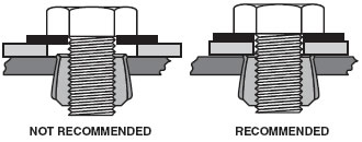
AVK recommends that the mating part comes in contact with the head of the A-T Series™ Insert. If a gap or clearance hole exists between the mating part and the A-T Series™ Insert, the threaded nut portion may rotate or pull through the parent material.
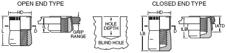

Closed End
Thread area is enclosed eliminating leakage past the threads from either side of the application.
THE A-T SERIES™ INSERT - THREAD SIZES
UNIFIED(INCH) SIZES
| Thread Size |
Thread Call Out |
HD ±.005 |
L ±.015 |
D Max. |
IL Max. |
LB ±.015 |
ILB Max. |
IATD** Max. |
Hole Depth Min. |
| 4-40 UNC | 440 | .211 | .370 | .1875 | .205 | .660 | .495 | .395 | .400 |
| 6-32 UNC | 632 | .240 | .370 | .2185 | .205 | .675 | .505 | .410 | .400 |
| 8-32 UNC | 832 | .269 | .370 | .2495 | .205 | .675 | .505 | .410 | .400 |
| 10-24 UNC | 1024 | .306 | .370 | .2805 | .205 | .685 | .520 | .385 | .400 |
| 10-32 UNF | 1032 | .306 | .370 | .2805 | .205 | .685 | .520 | .385 | .400 |
| 1/4-20 UNC | 420 | .400 | .515 | .3745 | .275 | 1.005 | .760 | .615 | .540 |
| 5/16-18 UNC | 518 | .528 | .615 | .4995 | .325 | 1.065 | .770 | .630 | .640 |
| 3/8-16 UNC | 616 | .588 | .745 | .5615 | .390 | 1.450 | 1.095 | .890 | .770 |
| 1/2-13 UNC | 813 | .800 | .935 | .7485 | .485 | NA | NA | NA | .960 |
METRIC SIZES
| Thread Size |
Thread Call Out |
HD ±0,13 |
L ±.0,38 |
D Max. |
IL Max. |
LB ±0,38 |
ILB Max. |
IATD** Max. |
Hole Depth Min. |
| M3x0,5 ISO | 350 | 5,36 | 9,40 | 4,76 | 5,21 | 16,77 | 12,57 | 10,03 | 10,16 |
| M4x0,7 ISO | 470 | 6,83 | 9,40 | 6,34 | 5,21 | 17,15 | 12,83 | 10,41 | 10,16 |
| M5x0,8 ISO | 580 | 7,77 | 9,40 | 7,12 | 5,21 | 17,40 | 13,21 | 9,78 | 10,16 |
| M6x1,0 ISO | 610 | 10,16 | 13,08 | 9,51 | 6,99 | 25,53 | 19,30 | 15,62 | 13,72 |
| M8x1,25 ISO | 8125 | 13,41 | 15,62 | 12,69 | 8,26 | 27,05 | 19,56 | 16,00 | 16,26 |
| M10x1,5 ISO | 1015 | 14,94 | 18,92 | 14,26 | 9,91 | 36,83 | 27,81 | 22,61 | 19,56 |
| M12x1,75 ISO | 12175 | 20,32 | 23,75 | 19,01 | 12,32 | NA | NA | NA | 24,38 |
THE A-T SERIES™ INSERT
HOLE SIZE / MATERIAL THICKNESS CHART
Installation hole size for the A-T Series™ Insert is determined by the parent material’s thickness and density. The thicker the material the larger the hole required to allow full 360° installation swaging. The application should be tested before hole size is specified.
UNIFIED(INCH) SIZES
| Thread Size |
.030-.090 Mat. Thickness | .091-.124 Mat. Thickness | .125-.186 Mat. Thickness | .187-Over Mat. Thickness | ||||
| Drill Size | Decimal | Drill Size | Decimal | Drill Size | Decimal | Drill Size | Decimal | |
| 4-40 UNC | 3/16 | .1875 | #10 | .1935 | #10 | .1935 | #9 | .1960 |
| 6-32 UNC | 7/32 | .2188 | #2 | .2210 | #1 | .2280 | #1 | .2280 |
| 8-32 UNC | 1/4 | .2500 | “F” | .2570 | 17/64 | .2656 | 17/64 | .2656 |
| 10-24 UNC | 9/32 | .2812 | “L” | .2900 | “L” | .2900 | 19/64 | .2969 |
| 10-32 UNF | 9/32 | .2812 | “L” | .2900 | “L” | .2900 | 19/64 | .2969 |
| 1/4-20 UNC | 3/8 | .3750 | 3/8 | .3750 | “W” | .3860 | 25/64 | .3906 |
| 5/16-18 UNC | 1/2 | .5000 | 1/2 | .5000 | 33/64 | .5156 | 33/64 | .5156 |
| 3/8-16 UNC | 9/16 | .5625 | 9/16 | .5625 | 37/64 | .5781 | 37/64 | .5781 |
| 1/2-13 UNC | 3/4 | .7500 | 49/64 | .7656 | 25/32 | .7810 | 51/64 | .7970 |
METRIC SIZES
| Thread Size |
0,76-2,29 Mat. Thickness | 2,31-3,15 Mat. Thickness | 3,17-4,72 Mat. Thickness | 4,72-Over Mat. Thickness | ||||
| Drill Size | Decimal | Drill Size | Decimal | Drill Size | Decimal | Drill Size | Decimal | |
| M3x0,5 ISO | 4,75 | .1875 | 4,90 | .1935 | 4,90 | .1935 | 4,97 | .1960 |
| M4x0,7 ISO | 6,35 | .2500 | 6,52 | .2570 | 6,74 | .2656 | 6,74 | .2656 |
| M5x0,8 ISO | 7,14 | .2812 | 7,36 | .2900 | 7,36 | .2900 | 7,54 | .2969 |
| M6x1,0 ISO | 9,52 | .3750 | 9,52 | .3750 | 9,80 | .3860 | 9,92 | .3906 |
| M8x1,25 ISO | 12,70 | .5000 | 12,70 | .5000 | 13,09 | .5156 | 13,09 | .5156 |
| M10x1,5 ISO | 14,28 | .5625 | 14,28 | .5625 | 14,68 | .5781 | 14,68 | .5781 |
| M12x1,75 ISO | 19,05 | .7500 | 19,44 | .7656 | 19,83 | .7810 | 20,24 | .7970 |
- FINISH: The standard specified finishes for the A-T Series™ Insert are cadmium and tin. Alteration to these finishes will reduce performance.
- *THREAD CLASS: The A-T Series™ Insert internal threads are manufactured oversized to compensate for resulting thread portion shrinkage during the installation swaging process. They are not gaugeable prior to or after installation but will be compatible with Class 2A/3A or 6g screws after installation.