A-S Series™ Stud Insert


The A-S Series™ functions in the same way as the A-L Series™ but has the added feature of a protruding stud.
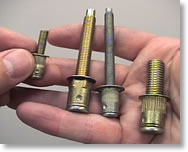
The A-S Series™ Stud Threaded Insert offers a unique design advantage in that once installed, a threaded stud is left protruding from the workpiece. Component parts can be located on the stud until final assembly is accomplished with a mating nut. The A-S Stud Insert is an ideal alternative to clinch or weld studs. The A-S Insert is designed to be used with Grade 5 or Metric Class 8.8/9.8 non thread locking type nuts.
The A-S Series™ Stud Threaded Insert is installed using AVK’s ARO brand Pneumatic Tools or AVK’s SPP™ Pneumatic/Hydraulic Tools. These tools can be located at any position on your assembly line. The A-S Stud can be installed either before or after finish.
SPINWALL TECHNOLOGY™
HOW HOLE FILL WORKS FOR YOU
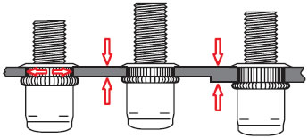
As the A-S Series™ is installed, the knurled body expands 360° FILLING THE HOLE. This feature provides exceptional torque strength and vibration resistance.

The installation tool then continues to install the stud forming a backside flange even in variable thickness material — WITHOUT ADJUSTMENT.

Sealed Head
A PVC foam seal is bonded to the underside of the head and when installed provides a weathertight seal. Contact AVK for a sales drawing.

Wedge Head
The addition of wedges under the head provides even greater torque capability, especially in soft or thin materials, and is excellent for electrical grounding applications.

Hex Body
The hex shell offers exceptional resistance to spinning once installed. Also available in full body hex version.

Dog Point
An optional Dog-Point provides ease in installing mating hardware and reduces the possibility of cross-threading. AVK offers Dog-Points in a variety of configurations.
Step 1
The operator 1/4 turns the AVK fastener on to the tool mandrel and places it into the hole. Operator then presses the top trigger on the tool and the AVK part installs.
Step 2
Once hole fill is complete, the AVK fastener forms its backside flange behind the parent material and the tool stalls.
Step 3
The operator reverses the tool and proceeds to attach the mating component using the appropriate mating hardware. The entire installation sequence of the AVK fastener takes 3 seconds or less.
Notes:
The operator can install the AVK fastener into two different material thickness’. This is the key benefit of the AVK System. You are able to install our products into single, variable or multiple thickness materials without tool adjustment.
During installation the AVK fastener expands within the hole Filling The Hole. This assures excellent spin out resistance and is a feature unique to AVK fasteners.
AVK fasteners are designed to be installed right on your assembly line either before or after paint or finish is applied to your product. This saves space and improves process flow.
ASS3T-420-165-625
| AS | ( ) | ( ) | - ( ) | - ( ) | - ( ) | ( ) | ||||||||||||||||||||||||||||||||
|
|
|
||||||||||||||||||||||||||||||||||||
|
|
|
|
|
|
|
||||||||||||||||||||||||||||||||
* Special order items are subject to minimum order requirements. Contact AVK for details.

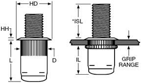
THE A-S SERIES™ STUD - THREAD SIZES
*NOTE: The ISL Dimension shown below is the height of the installed stud at max grip. The height of the stud will increase if it is installed into thinner material. To calculate actual ISL use this formula: Max grip - actual grip + ISL = Actual ISL
Thread Specifications:
Unified - 2A/21 per ASME B1.1
Metic - 6G/21 per ASME B1.13M
Unified (Inch) and Metric Thread Sizes
| Thread Size |
Thread Call Out |
Grip Range |
Grip Call Out |
Stud Lengths | Hole Size +.006 -.000 |
HD ±.010 ±0.25* |
HH ±.003 |
L ±.020 |
D Max. |
IL Max. |
||
| ISL Call Out |
ISL Call Out |
ISL Call Out |
||||||||||
| 6-32 UNC | 632 | .020-.080 | 80 | .500 500 |
.625 625 |
.750 750 |
17/64 (.2656) | .390 | .030 | .485 | .265 | .360 |
| 6-32 UNC | 632 | .080-.130 | 130 | .450 450 |
.575 575 |
.700 700 |
17/64 (.2656) | .390 | .030 | .535 | .265 | .360 |
| 8-32 UNC | 832 | .020-.080 | 80 | .500 500 |
.625 625 |
.750 750 |
17/64 (.2656) | .390 | .030 | .485 | .265 | .360 |
| 8-32 UNC | 832 | .080-.130 | 130 | .450 450 |
.575 575 |
.700 700 |
17/64 (.2656) | .390 | .030 | .535 | .265 | .360 |
| 10-24 UNC | 1024 | .020-.130 | 130 | .500 500 |
.625 625 |
.750 750 |
19/64 (.2969) | .415 | .030 | .545 | .296 | .380 |
| 10-24 UNC | 1024 | .130-.225 | 225 | .405 405 |
.530 530 |
.655 655 |
19/64 (.2969) | .415 | .030 | .655 | .296 | .380 |
| 10-32 UNF | 1032 | .020-.130 | 130 | .500 500 |
.625 625 |
.750 750 |
19/64 (.2969) | .415 | .030 | .545 | .296 | .380 |
| 10-32 UNF | 1032 | .130-.225 | 225 | .405 405 |
.530 530 |
.655 655 |
19/64 (.2969) | .415 | .030 | .655 | .296 | .380 |
| 1/4-20 UNC | 420 | .027-.165 | 165 | .625 625 |
.8125 8125 |
1.000 1000 |
25/64 (.3906) | .500 | .030 | .670 | .390 | .465 |
| 1/4-20 UNC | 420 | .165-.260 | 260 | .530 530 |
.7175 7175 |
.905 905 |
25/64 (.3906) | .500 | .030 | .770 | .390 | .465 |
| 5/16-18 UNC | 518 | .027-.150 | 150 | .625 625 |
.875 875 |
1.125 1125 |
17/32 (.5312) | .685* | .035 | .810 | .530 | .600 |
| 5/16-18 UNC | 518 | .150-.312 | 312 | .463 463 |
.713 713 |
.963 963 |
17/32 (.5312) | .685* | .035 | .925 | .530 | .555 |
| 3/8-16 UNC | 616 | .027-.150 | 150 | .750 750 |
1.000 1000 |
1.250 1250 |
17/32 (.5312) | .685* | .035 | .810 | .530 | .600 |
| 3/8-16 UNC | 616 | .150-.312 | 312 | .588 588 |
.838 838 |
1.088 1088 |
17/32 (.5312) | .685* | .035 | .925 | .530 | .535 |
| Thread Size |
Thread Call Out |
Grip Range |
Grip Call Out |
Stud Lengths | Hole Size +0,15 -0,00 |
HD ±0,25 ±0,64* |
HH ±0,08 |
L ±0,50 |
D Max. |
IL Max. |
||
| ISL Call Out |
ISL Call Out |
ISL Call Out |
||||||||||
| M4x0,7 ISO | 470 | 0,50-2,00 | 2.0 | 12,0 12 |
15,0 15 |
20,0 20 |
6,75 | 9,91 | 0,76 | 12,32 | 6,73 | 9,15 |
| M4x0,7 ISO | 470 | 2,00-3,30 | 3.3 | 10,7 10.7 |
13,7 13.7 |
18,7 18.7 |
6,75 | 9,91 | 0,76 | 13,59 | 6,73 | 9,15 |
| M5x0,8 ISO | 580 | 0,50-3,30 | 3.3 | 12,0 12 |
15,0 15 |
20,0 20 |
7,60 | 10,54 | 0,76 | 13,84 | 7,52 | 9,65 |
| M5x0,8 ISO | 580 | 3,30-5,70 | 5.7 | 9,6 9.6 |
12,6 12.6 |
17,6 17.6 |
7,60 | 10,54 | 0,76 | 16,64 | 7,52 | 9,65 |
| M6x1,0 ISO | 610 | 0,70-4,20 | 4.2 | 15,0 15 |
20,0 20 |
25,0 25 |
10,00 | 12,70 | 0,76 | 17,02 | 9,91 | 11,81 |
| M6x1,0 ISO | 610 | 4,20-6,60 | 6.6 | 12,6 12.6 |
17,6 17.6 |
22,6 22.6 |
10,00 | 12,70 | 0,76 | 19,56 | 9,91 | 11,81 |
| M8x1,25 ISO | 8125 | 0,70-3,8 | 3.8 | 16,0 16 |
22,0 22 |
28,0 28 |
13,50 | 17,40* | 0,89 | 20,57 | 13,46 | 15,24 |
| M8x1,25 ISO | 8125 | 3,8-7,90 | 7.9 | 11,9 11,9 |
17,9 17,9 |
23,9 23,9 |
13,50 | 17,40* | 0,89 | 23,50 | 13,46 | 14,10 |
| M10x1,5 ISO | 1015 | 0,70-3,8 | 3.8 | 20,0 20 |
25,0 25 |
30,0 30 |
13,50 | 17,40* | 0,89 | 20,57 | 13,46 | 15,24 |
| M10x1,5 ISO | 1015 | 3,8-7,90 | 7.9 | 15,9 15,9 |
20,9 20,9 |
25,9 25,9 |
13,50 | 17,40* | 0,89 | 23,50 | 13,46 | 13,60 |
- NOTE 1: Grip range stated in the dimensional chart above can be achieved using pull type installation tools and may be variable based on hole size and parent material density. AVK recommends trial installations to determine actual grip range in the application.
- NOTE 2: Grip ranges will be less than stated above when using torque type installation tools. Grip range will be affected by the tool RPM speed, stall torque, hole size and parent material density. AVK recommends trial installations to determine actual grip. See page 33 for torque tool selection guidelines.